Modular RIAA Phono Stage
A deliberately over-engineered modular phono preamp platform with custom power, control, analog audio, and 3D-printed enclosure design.
Modular RIAA Phono Stage
Overview
The Modular RIAA Phono Stage is a deliberately over-engineered one-off audio project built around a configurable power-supply platform, an MCU-based control board, swappable analog processing modules, and a custom 3D-printed enclosure.
At a basic level, the project is a phono preamp for turntables. The more interesting part is how it is built. Rather than designing the simplest possible RIAA preamp circuit, I designed the project as a modular mixed-signal audio platform. The system is split into separate boards for power, control, analog processing, output buffering, and user interaction.
The result is a compact audio device that combines custom PCB design, USB-C powered supply architecture, analog signal processing, MCU-controlled power sequencing, front-panel UX, and enclosure design into a single prototype.
Modular RIAA Phono Stage Gallery
Project Goals
The goal of this project was not simply to make a working phono stage. The goal was to explore how a small analog audio device could be structured as a modular platform.
The design separates the system into functional sections so that each part can be changed, tested, or reused independently. The power supply board acts as an interconnect platform for different power modules. The MCU board handles monitoring, control, sequencing, and user interaction. The analog side supports swappable processing boards, with this prototype using left and right RIAA phono stage modules.
This approach made the project much more complex than necessary for a one-off phono preamp, but that complexity was intentional. The project became a way to experiment with product-style audio architecture, mixed-signal layout, controlled startup behaviour, and mechanical integration.
System Architecture
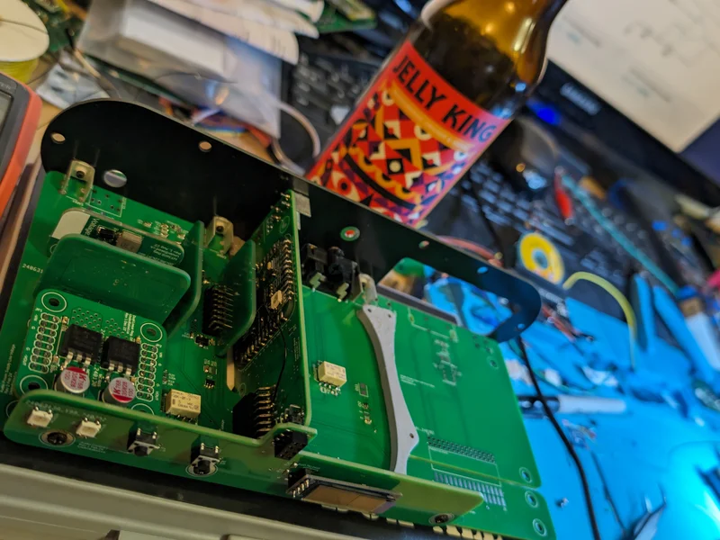
The design is divided into three main internal regions: power on the left, digital control in the middle, and analog audio on the right.
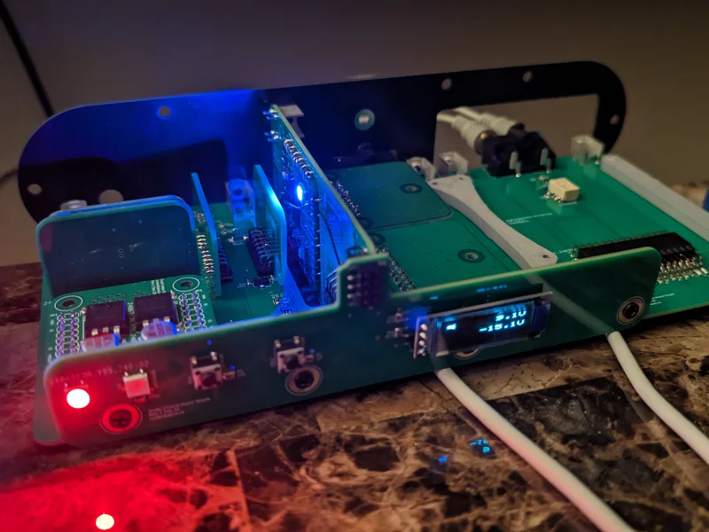
The power-supply board provides the various rails and control signals needed by the rest of the system. The MCU board is mounted sideways between the power and analog sections, with the digital electronics facing toward the power side. The analog circuitry is kept on the opposite side of the MCU board to help reduce noise coupling into the audio path.
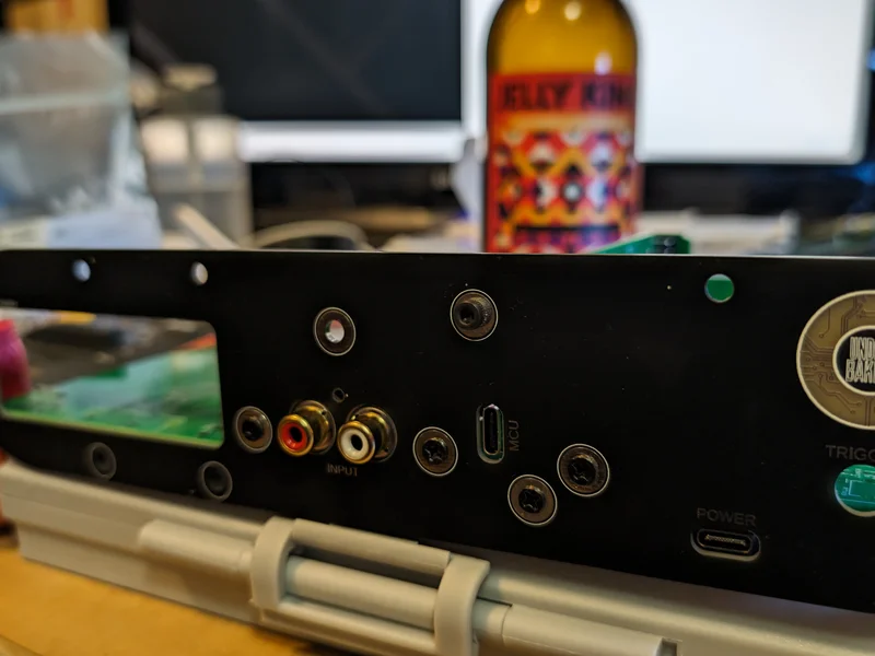
The front-panel board provides the user-facing controls, status LEDs, and small display. The rear panel exposes the RCA input, USB-C power input, MCU access port, trigger input, and branding.
This layout allowed the project to be developed as a complete device rather than a collection of loose boards on a bench.
Power Supply Design
The power-supply board is essentially an interconnect board for multiple submodules. It was designed so that the power architecture could be customized depending on what the rest of the unit needed.
The power system includes USB-C Power Delivery negotiation, two separate 5 V step-down modules, optional voltage boosting, symmetrical analog power rails, and post-regulation using LDOs. One 5 V supply is used for standby power, while the second is used for logic circuits that only need to be powered when the unit is on.
The board also includes 2 amp rated communication relays and op-amp circuitry that scales the positive and negative analog rails so they can be measured by the MCU. This allows the controller to verify the supply rails before enabling the rest of the unit.
This makes the power supply more than a simple regulator board. It becomes a controlled power platform with monitoring, sequencing, and configurable rail generation.
MCU and Control Electronics
The MCU board acts as the controller for the system. It connects to the power-supply board, the analog board, and the front-panel UX board.
The board is mounted sideways, with the digital electronics facing the power-supply side of the device. It is a four-layer PCB, with the bottom layer used as a ground plane to help isolate digital noise from the analog section.
The MCU is responsible for monitoring the power rails, controlling startup behaviour, handling front-panel interaction, and controlling the output mute circuit. This allows the device to avoid powering the analog output stage before the rails are ready, reducing the chance of pops or unwanted startup noise.
Analog Audio Design
The analog side of the project is also modular. The signal path is divided into an input board, processing boards, and an output stage.
In this prototype, the processing boards are left and right RIAA phono stage modules. Each channel is handled on its own board, allowing the analog processing section to be treated as a swappable part of the system rather than being permanently tied to the rest of the device.
After the RIAA processing stage, the signal passes through an output stage containing a buffer and mute circuit. The mute circuit is controlled by the MCU so the output can remain muted during power-up and shutdown, helping avoid audible pops.
Mechanical Design
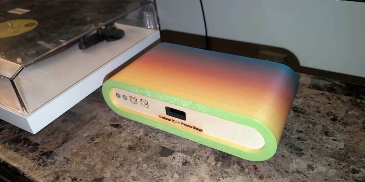
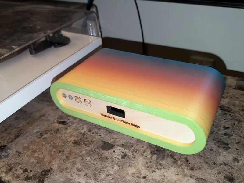
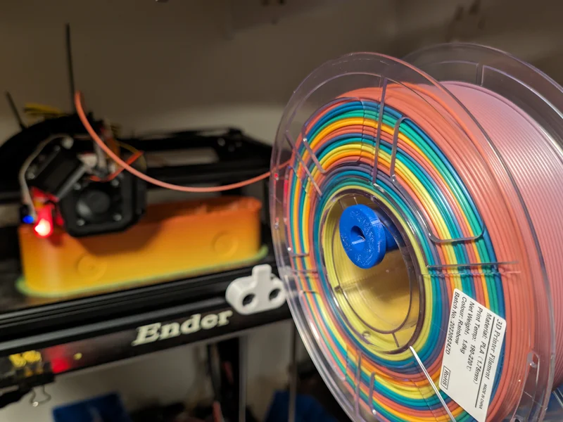
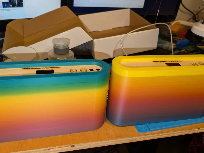
The enclosure was designed as a custom 3D-printed case with a rounded rectangular form and a contrasting front label area. The colourful filament gives the device a playful appearance that contrasts with the fairly serious electronics inside.
The enclosure includes space for the internal PCB stack, front-panel display, status LEDs, buttons, rear-panel connections, and mounting hardware. Multiple enclosure versions were printed to test the fit, appearance, and final presentation of the device.
The goal was to make the project feel like a finished object rather than a bare bench prototype. The final enclosure gives the device a product-like form while still keeping the personality of a one-off maker project.
Prototype and Bring-Up
The project moved through several stages, including PCB design, board assembly, bench testing, internal mechanical fitting, panel integration, enclosure printing, and powered system testing.
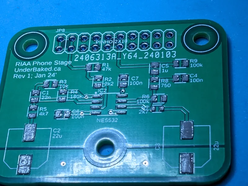
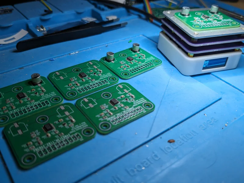
The RIAA processing boards were assembled and tested separately before being integrated into the larger system. The internal boards were then mounted into the chassis structure and connected to the front and rear panels.
The powered prototype includes working status indication, front-panel controls, display output, rear-panel connections, and the complete internal modular board stack.
My Role
I designed the project as a complete hardware and mechanical prototype, including the system architecture, electronics, PCB layout, board interconnect strategy, enclosure, and physical integration.
My work included:
- Defining the modular audio platform concept
- Designing the power-supply architecture
- Designing the custom PCBs and board interconnects
- Designing the MCU control and monitoring approach
- Designing the modular analog processing layout
- Building left and right RIAA phono stage processing boards
- Integrating relay control, rail monitoring, and mute control
- Designing the front-panel UX board
- Designing the rear-panel I/O layout
- Designing and printing the custom enclosure
- Assembling and testing the working prototype
Skills Demonstrated
This project demonstrates a combination of analog audio design, power electronics, mixed-signal PCB layout, embedded control, mechanical design, and product integration.
Key skills demonstrated include:
- Custom PCB design
- Modular hardware architecture
- Analog audio circuit design
- RIAA phono stage implementation
- Op-amp circuit design
- USB-C powered system design
- DC-DC conversion
- Symmetrical power rail generation
- LDO post-regulation
- Power sequencing
- MCU-based rail monitoring
- Relay and mute circuit control
- Mixed-signal layout strategy
- Ground plane isolation
- Front-panel UX integration
- 3D-printable enclosure design
- Prototype assembly and bring-up
- Product-style mechanical integration
Current Status
A working prototype has been assembled with the custom power, MCU, analog, front-panel, and enclosure components.
The project currently exists as a functional one-off rather than a planned commercial product. Its main value is as a technical exploration of modular analog audio design, configurable power architecture, and full-device prototype development.
Summary
The Modular RIAA Phono Stage is more than a simple phono preamp. It is a compact mixed-signal audio platform built around modular power, control, analog processing, and enclosure design.
The project combines serious electronics design with a playful 3D-printed enclosure, turning an intentionally overbuilt one-off into a complete working prototype. It demonstrates the process of taking an idea from system architecture and PCB design through assembly, testing, mechanical integration, and final presentation.
The result is very much an UnderBaked project: technically ambitious, slightly ridiculous, and intentionally not another boring black audiophile box.